|
|
3D Print Radio Parts (N4HCI) |
3D Printing
The "Maker' hobby has been growing in popularity for years. The
term "Maker' does not describe any one thing, but is a collective term
for people making their own proejcts. It easily includes sewing,
hand crafts, wood work, metal work, foundry work, making things with
Arduino computers, etc.
3D printing is part of the maker hobby and one that I have only
recently joined. 3D printers suitable for home use come in many
sizes, different eases of use, and prices. I selected a very
inexpensive Chinese product with a large build volume (ANET E12) which I
bought in early February 2017. [CAUTION. This is a rather
high maintenance 3D printer. A number of the more expensive units
are much easier to use and lower maintenance but it seems that part of
the 3D printer 'Maker" hobby is to improve the printer itself and make
it better - but that is a story for a different time.]
For Hams, the 3D printer provides a means to manufacture parts for your
radio, the shack, and your antenna. I have seen projects where people make
knobs, buttons, labels, CW keys, microphones,
coil winding spools, kit enclosures, portable satellite tracking
antennae, radio cases, microphone holders, chassis feet, stands for
positioning a raised radio front edge, Call Sign displays, antenna
insulators, etc.. Inspired by these efforts, I decided to
use my new 3D printer and see what I could do.
After a couple of months I have manufactured
- a microphone body and assembled it into a working microphone, and
- an adapter sleeve to allow use of available radio knobs on undersized
shafts
And following these modest starts, I am now working on the printing of
a home designed uBITX radio enclosure.
3D Printing Workflow
3D printing is a multi-step process. The first step is to either
acquire from someone who made it, or make a model yourself, of the
product to me printed. In my case, I use Adobe's Autodesk Fusion
360, a very capable design development platform. Other design
software, easier to
use but somewhat more limited in their abilities, exist, such as
TinkerCAD. The purpose of the modeling phase is to develop the
look and feel for the object, to include all dimensions of all
internal and external features necessary to the purpose of the object
being designed. At the end of the modeling phase, all of the
models parts must fit together just as they will when they exists a
physical objects. The end result of the design will be a file
saved in a format appropriate to the design software, but the design
software also needs to export the design in a format that can be read by
a 3D printer slicer program. A common file format for this purpose
is the .STL format.
The slicing program reads the STL file and presents the model on a
visualization of the 3D printer bedplate, where it can be manipulated
into the proper position for printing, and where the user specifies the
specific printing facts and instructions necessary for the printer to do
its job. These include such things as nozzle size, printing medium
(type and size of type of plastic filament being used), layer size, wall
thickness, printer head travel speeds, temperatures for the nozzle (as
appropriate to melt the plastic filament type) and bedplate (help adhere
the print to the bedplate during the printing process), and whether to
make the interior solid or filled with an Infill of less than 100%
plastic. Once these have been specified, the program slices the
object into a series of layer by layer instructions that tell the
printer how to move the print head, and bedplate, and how much plastic
to extrude so that the printer can make each layer. In my case, I
use Cura, a free slicer program from the Ultimaker 3D printer folks.
The output program from the slicer program that is used by most printers
is usually in .GCODE format.
The printer then reads the GCODE file and prints the object described by
it, layer by layer, until finished. Print layers can be 0.1 mm in
vertical thickness, taking 10 layers to make 1 mm and a large number of
layers to make an object of any size.
Printing can take a long while. Prints lasting more than a day are
fairly common and the uBITX enclosure described below will take over two
days.
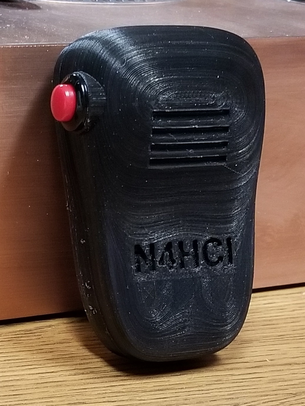
Microphone
While waiting 2 months for delivery of my uBITX radio, I decided to make
its enclosure out of 2-sided PCB material (see that project
here) and to make a microphone
out of a Radio Shack push button, an electret microphone element, and a
coiled 4-wire telephone cable, all available from the junk box.
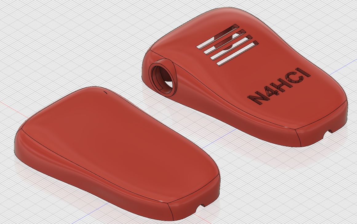
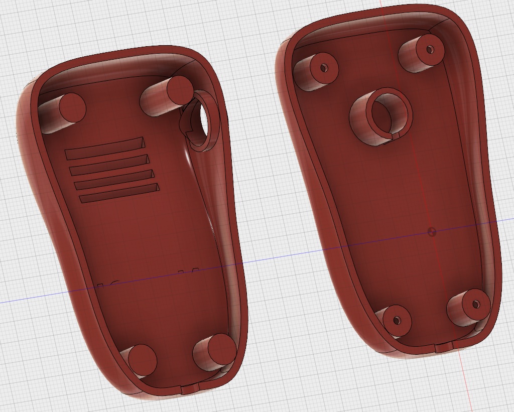
The microphone model design needed to be two parts that included a front
shell, a rear shell. The shells needed to include a hole for the
microphone cable, a hole to mount the push button, slots for my voice to
pass through to reach the electrect element, an internal bracket into
which the electret element would snuggly fit, and some posts that
would allow the shells to be screwed together. At the end of the
modeling, the microphone looked like:
A video short of the printer at about 10% of the shell back can be seen
here.
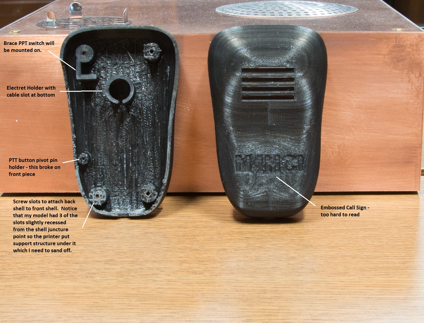
For me at least, 3D printing is an iterative process with early prints
not necessarily being the final prints. Errors discovered in the early
prints lead to design changes and a reprint. The above design was
the 2nd design after printing the initial design (see below) and deciding that it
needed to be changed. The 2nd design eliminated the original
intention to 'make' the PTT switch instead of installing it, fixed some
dimensional errors, and made the embossed call sign deeper.
The end result of the redesign was

Power/Volume Knob Adapter
This project was mostly taking dimensions of a shaft and a knob's shaft
well with a micrometer and then designing and printing an adapter to
allow a knob to be installed on an undersized potentiometer shaft and
stay centered when it was rotated. It took several tries to get
the dimensions just right.
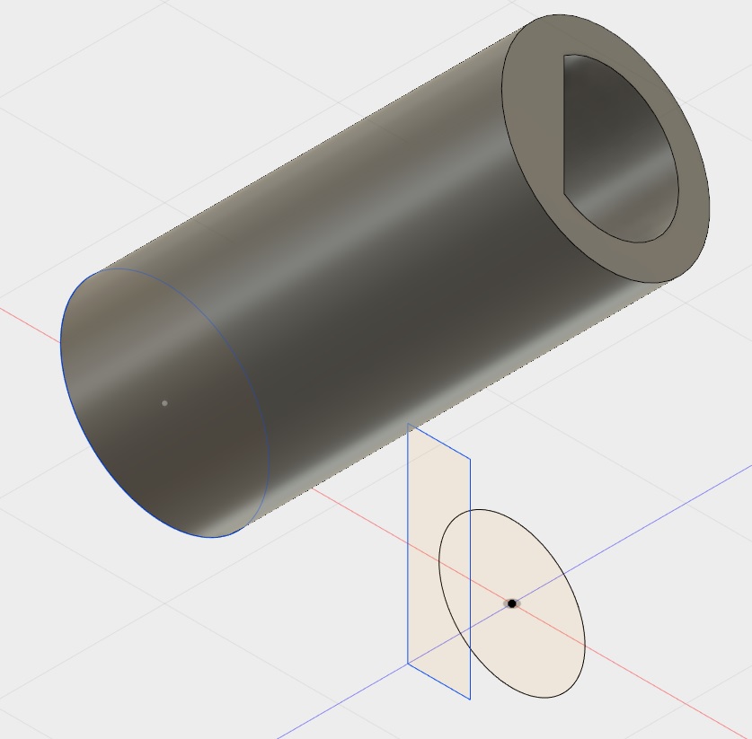
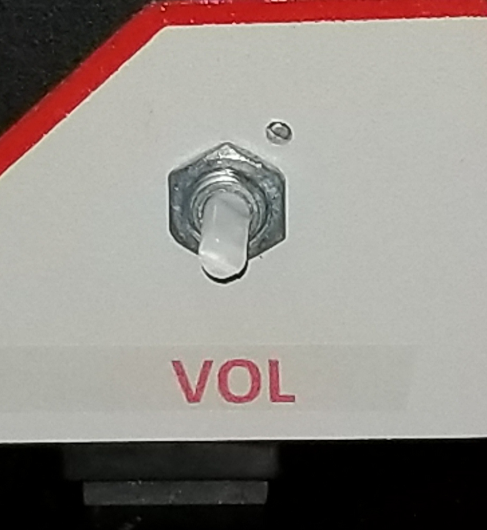
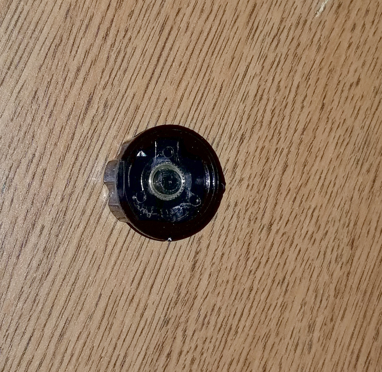
The design model, the shaft needing an adapter, and the knob with the
adapter inserted into it are shown above.
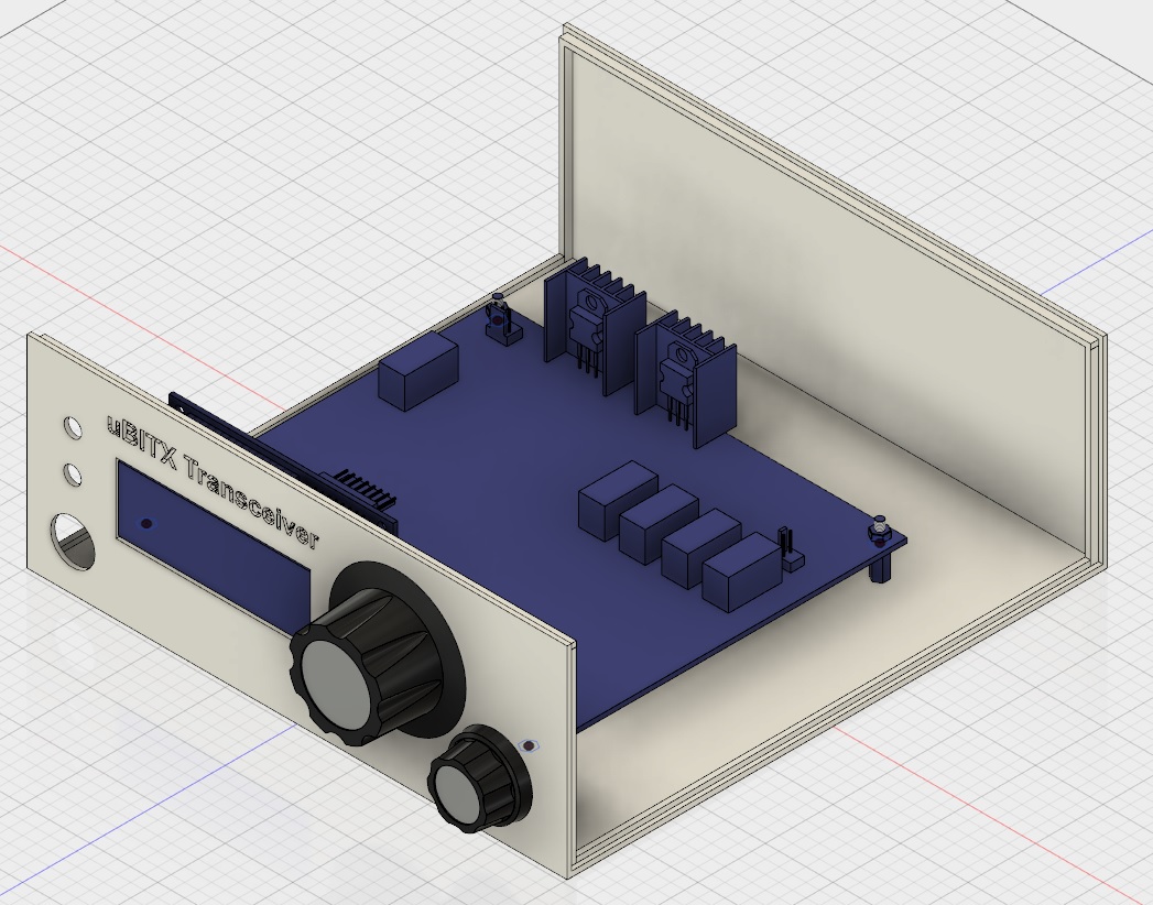
uBITX Enclosure - Work In Progress
This project is an unprinted work in progress and is currently still in
the design phase. Ultimately It is envisioned to be printed for a
friend who is getting a uBITX radio for his future birthday. This
project is attempting to solve some issues I've had with putting radios
into enclosures - specifically
- eliminating the need to cut, drill, or knibble holes into the
enclosure in order for parts, air, or sound to pass through the
enclosure walls
- having precise measurements of each needed penetration and modeling
them so that they can be placed properly to simply assemble the radio
parts
- being able to visualize 'what-if' design options easily, and make
design adjustments with minimum fuss and bother
After modeling component parts of the uBITX radio circuit boards, LCDs,
and stand-offs, the 'radio' model has been dropped into the model of the
enclosure to optimize fitment and try various designs for placement of
other parts (tuning control, power/volume control, microphone socket,
speaker/headphone socket, key socket, SO-239, power plug) while ensuring
no fouls with the radio or critical accesses to part of the radio.
The following is a model picture for one of the 'what-if' placements of
front panel parts.
Adding remaining front panel model parts, locating and adding rear panel
parts, creating a 'top' to the enclosure and 'attaching' a model of the
internal speaker remain.
Then it will be time to print. The bottom and the top are each
expected to take more than a day to print.
.